Posted on September 2, 2019 by Justin Ong and Ron Munson
Carbon capture, utilization and storage, aka “CCS” or “CCUS”, refers to the removal of carbon dioxide from the waste streams of industrial processes or from the atmosphere, for storage underground or “recycling” into new products. Much like the term “energy efficiency”, carbon capture is an umbrella term for many technologies. This overview describes the main technology types.
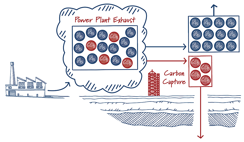
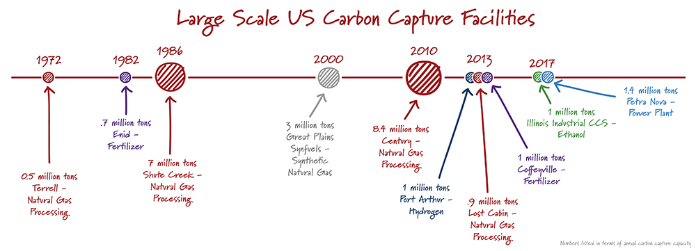
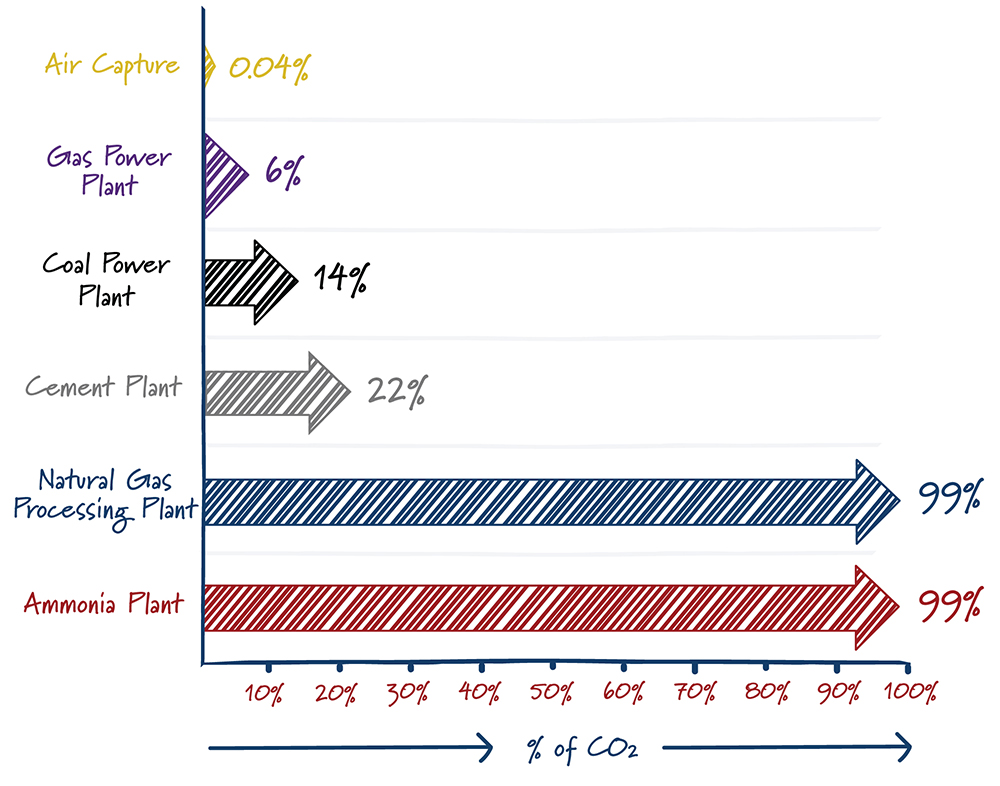
Finding a needle in a haystack is much easier when there are more needles. In a similar way, carbon capture is easier with high carbon dioxide concentrations. The energy required – and hence the cost – to separate CO2 from other gases increases rapidly as the concentration of carbon dioxide decreases. It’s not a surprise then that most carbon capture projects are at ethanol plants, natural gas processing facilities, and others that produce gases with high concentrations of carbon dioxide.
Developers:
Description:
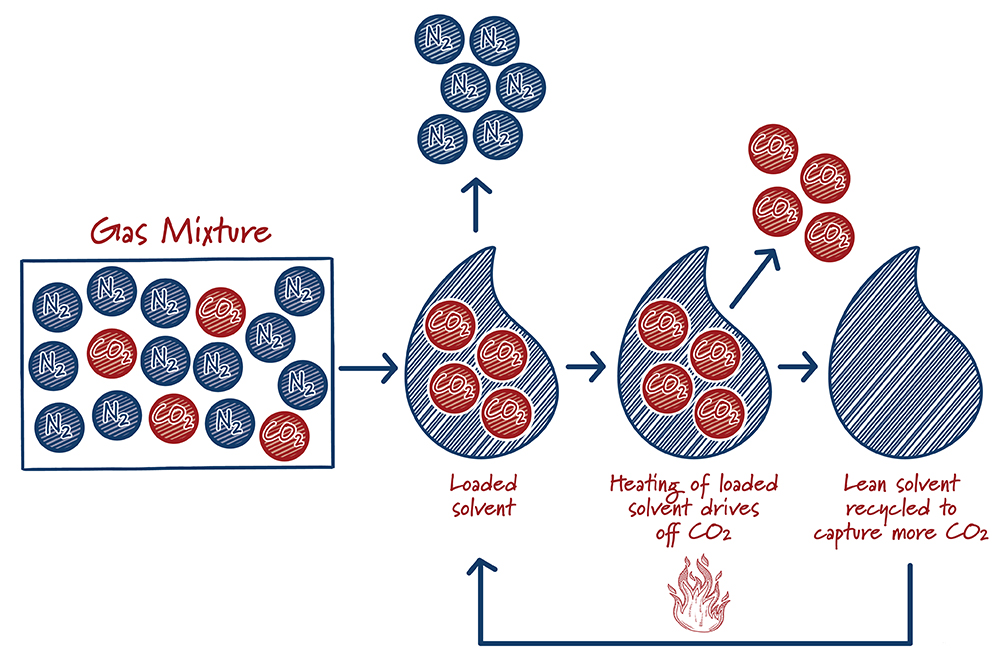
Solvents are specially formulated liquids that selectively “grab” carbon dioxide from a mixture of other gases. The solvent absorbs the carbon dioxide, like dissolved carbon dioxide in soda. However, unlike soda, the carbon dioxide is chemically bound to the solvent, so that it doesn’t just fizz away. After the solvent absorbs as much CO2 as it can, the “loaded” solvent is heated to release the captured carbon dioxide and the solvent is recycled back into the carbon capture system.
Solvents are the most mature carbon capture technologies. They’ve been in use for decades in the oil and gas industry for removing impurities, and have been the historic focal point of R&D. Research is underway to improve the efficiency of this catch-and-release process, as well as improving the durability of the solvents. The Petra Nova facility near Houston is the first commercial scale carbon capture facility at a U.S. power plant. It uses a Mitsubishi Heavy Industries solvent that began development in the early 1990s. The solvent steadily graduated from laboratory testing, to small megawatt-scale testing, a large pilot at an operating power plant, and finally to full size that captures the equivalent emissions of 350,000 cars.
Case study:
One characteristic of current solvent systems is that the majority is actually water and less than half actually captures carbon dioxide. Although water does not remove CO2, it is needed to reduce the viscosity and corrosiveness of the solvent. The energy needed to heat, cool and move the water in the capture system adds significant costs. Colorado-based ION Engineering has developed a capture system that replaces the water in the solvent mixture with organic compounds. The ION approach reduces the amount of water by about 60%. This results in faster uptake of carbon dioxide, which allows for smaller equipment and reduces the energy required to run the system. Water is difficult to completely eliminate from the system because it commonly enters the capture system with the carbon dioxide-containing gas as a common byproduct of power plants and other industrial sources.
Developers
Description:
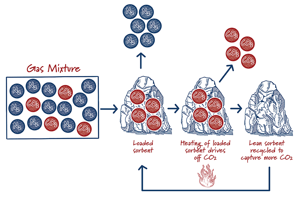
Sorbents and solvents are similar, but in solvents the CO2 is absorbed into a liquid whereas for sorbents the CO2 is adsorbed onto solids. After the sorbent captures and releases the CO2, the sorbent can be used again. Releasing CO2 is typically accomplished by either reducing the pressure or by increasing the temperature. Although solid adsorption-based approaches have been used for decades in various process industries, their use for carbon capture is at an earlier stage of development than solvents. Active research and development efforts show significant promise for decreasing costs and improving performance.
How do sorbents work?
Case study:
Lawrence Berkeley National Laboratory is developing a technology that uses novel materials (metal-organic frameworks or “MOFs”) that contain channels where CO2 molecules are adsorbed. The channels are filled with dangling chemicals (“amines”) that grab CO2 molecules. Like a baton in a relay race, the amines work together by continuously “handing off” individual carbon dioxide molecules to one another in a stepwise fashion to move carbon dioxide down the channel. The process is attractive because it is highly customizable and relatively compact. Preliminary analyses indicate that the technology can meet the Department of Energy’s long-term capture cost goals.
Description:
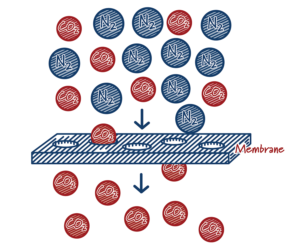
Membrane systems capture carbon dioxide by putting the gas stream containing CO2 in contact with specially engineered materials called membranes. Much like a colander lets water (and no pasta) flow through it, membranes let CO2 move through at a much higher rate than other gases. Performance is largely defined by how quickly gas molecules can move through the membrane material (“permeance”) and the degree to which one molecule passes through the membrane compared to another molecule (“selectivity”). Ideally, membrane materials would have both high permeance and selectivity. In practice, however, they typically work against one another. High permeance materials are typically not very selective and highly selective materials tend to have low permeance. Driven by materials and process improvements, membranes have emerged as attractive capture options in some applications.
How do membranes work?
Case study:
Membrane Technology and Research has been involved in the development of an advanced PolarisTM membrane since 2007. Over that time they have increased the permeance of their membranes by 10 times, increased its durability and improved its energy efficiency. As part of the development process, they have operated their capture system for over 1,000 hours at the National Carbon Capture Center and have demonstrated that boiler operation is not substantially degraded in the presence of CO2 recycle that increases flue gas CO2 concentration, reducing cost. Recent analysis suggests that capture costs have been reduced to just over $40 per metric ton.
Description:
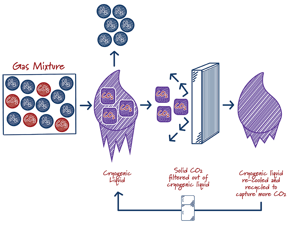
Cryogenic separation of gases has been done industrially since the early 1900s. The process typically involves cooling a gas mixture until it liquefies, then allowing the liquid to warm to the boiling points of individual components to produce a purified gas stream. Gases produced in this way are often very pure, but the process is energy-intensive, involving multiple refrigeration, compression and expansion steps that are typically driven by electricity. For carbon capture, the flue gas mixture is cooled down to very low temperatures until the CO2 solidifies into dry ice. The dry ice is then filtered out, pressurized, and prepared for storage or use. The process can be added directly onto the end of the end of a production facility and has no impact on the operation of the host facility. For example, it does not require the use of any steam that is typically used to generate electricity in a power production setting. In addition to removing CO2, the cryogenic process will also remove traditional air pollutants.
How do cryogenic systems work?
Case study:
Sustainable Energy Solutions estimates its cryogenic carbon capture technology reduces parasitic energy requirements and costs by about half compared to a conventional solvent-based process. It has been tested at small scales for power and industrial applications. In the process, flue gas is dried and then added to a cryogenic liquid, where it is cooled to the point CO2 freezes (about -120 °C!). The dry ice and the cryogenic liquid form a muddy mixture that is filtered to separate the liquid and solid streams. The solid CO2 stream is then warmed and liquefied under pressure. The cryogenic liquid stream is cooled and cycled back to be reused.
Description:
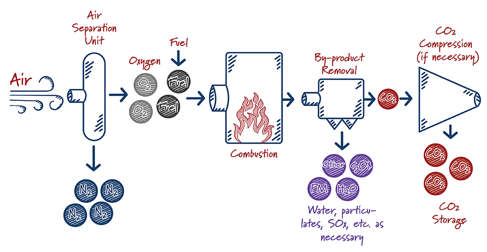
In oxy-combustion based systems, fuel is burned using nearly-pure oxygen rather than air (a mix of nitrogen and oxygen). This produces a waste gas stream that consists principally of CO2 and water, which can be fairly easily separated. The main gas separation process in oxy-combustion involves filtering O2 from the air prior to burning the fuel.
When oxy-combustion is paired with a supercritical CO2 power system – which uses hot, high-pressure CO2 to generate electricity rather than steam – the potential exists to operate at very high efficiency and capture nearly 100% of the CO2 generated. The equipment used is smaller than equivalent equipment used in traditional systems, resulting in lower capital costs and smaller overall footprint.
How do oxy-combustion systems work?
Case study:
North-Carolina based NET Power is currently testing a oxy-combustion pilot plant outside of Houston. The $150 million project promises to create a virtually zero-emission natural gas power plant. After combusting pressurized natural gas with pure oxygen, the resulting gas drives a specially-designed turbine to generate electricity. The gas leaving the turbine is rapidly cooled to remove water, recycle heat and, ultimately, leave a stream of nearly pure CO2 for use or storage.
Description:
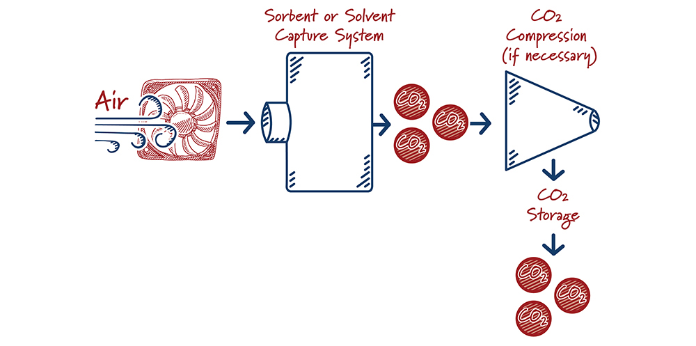
Direct air capture (“DAC”) is the process of mechanically removing carbon dioxide directly from the air. The most advanced climate models agree that negative emissions technologies, including DAC, are important tools for deep decarbonization. However, its estimated costs are higher than other types of carbon capture. Advantages of direct air capture projects include their ability to be sited virtually anywhere (reducing the need for extra infrastructure like carbon dioxide pipelines) and “rightsizing” projects to local carbon dioxide utilization demand.
Direct air capture is at a relatively early stage of development. Although the engineering approach mimics conventional solvent- and sorbent-based capture systems, the ultra-low CO2-concentration environment amplifies some of the challenges faced in conventional systems. Using the earlier needle in a haystack analogy, there are very few “needles” in this particular haystack.
How do direct air capture systems work?
Case study:
Carbon Engineering, a Bill Gates-backed company, is currently testing a 1 ton per day pilot system in British Columbia. Multiple large fans bring air into contact with a solvent solution. The solvent carrying the carbon dioxide is processed to create a concentrated CO2 stream and regenerated solvent. The company’s current cost estimates range from just under $150 per ton to over $260 per ton, and is targeting mature costs of less than $100 per ton.
Ron Munson is a principal at Cogentiv Solutions, a consulting firm specializing in energy and environmental management. Mr. Munson was a former technology manager at the Global CCS Institute and a Senior Engineer contracting to the National Energy Technology Laboratory. Justin Ong is a program director at ClearPath, a DC-based non-profit organization that specializes in clean energy policies that develop and demonstrate breakthrough technologies.
